Russian Rod Pentodes 1
Sub miniature Russian Valves (Tubes) of Rod Pentode type.

Common types available on eBay and other online resellers from Russia, Bulgaria and Ukraine.
All direct heated filament/cathode and about 8mm to 10mm glass with Anode on top wire.
For reliable longest life operate at less than 1.4V and more than 0.9V filament (not direct from Zinc, Alkaline, NiMH cells) and operate at less than maximum currents and voltages.
In English transliteration the Ж Cyrillic Character may be written j, sh, zh, SH or ZH
Typical Filament mA currents for 1.35V. VG2 is minimum at quoted HT and HT is “typical” not maximum
RL1 = Approx min Anode load for max power (K Ohms at listed HT).
RL2 = Approx max Anode Load for max gain, small signal (K Ohms at listed HT)
gm listed is below max listed but above minimum listed for 0.95V filament. It varies with HT and filament current more than 2:1
Pa is maximum Power, likely at higher HT than listed.
| Valve | Cyrillic |
f mA |
IaVg1=0 | Vg2 | HT |
Pa |
gm | IkMax |
RL1 | RL2 |
Notes |
|---|---|---|---|---|---|---|---|---|---|---|---|
| 1j17b | 1Ж17Б | 49 | 2.0 | 45 | 60 | 120 | 0.9 | 5.0 | 12 | 56 | Early model |
| 1j18b | 1Ж18Б | 24 | 0.9 | 45 | 60 | 80 | 0.9 | 5.0 | 18 | 100 | G3 & shield tied to f- wire, low Cag |
| 1j24b | 1Ж24Б | 13 | 0.8 | 45 | 60 | 25 | 0.7 | 1.6 | 27 | 180 | Lowest filament power Rod Pentode |
| 1j29b | 1Ж29Б | 54 | 5.5 | 90 | 90 | 300 | 2.0 | 8.0 | 10 | 39 | CT filament @ 26mA Series |
| 1j29b-v | 1Ж29Б-B | 54 | 5.5 | 90 | 90 | 300 | 2.0 | 8.0 | 10 | 39 | CT filament @ 26mA Series, more durable |
| 1j29b-r | 1Ж29Б-P | 54 | 5.5 | 90 | 90 | 300 | 2.0 | 8.0 | 10 | 39 | CT filament @ 26mA Series, Reliable & most Durable |
| 1j37b | 1Ж37Б | 59 | 2.5 | 45 | 60 | 150 | 1.1 | 4.5 | 10 | 56 | Dual G1 (1.5pF G1A, G1B) and no Shields. Mixer or AGC (not Osc/Mixer) |
| 1p24b | 1П24Б | 198 | 18 | 120 | 150 | 2500 | 2.5 | 25 | 5 | 22 | CT filament @ 98mA Series. 1W G2 and 800W peak |
| 1p24b-v | 1П24Б-B | 198 | 18 | 120 | 150 | 2500 | 2.5 | 25 | 5 | 22 | CT filament @ 98mA Series, more durable |
A study of 1j24b, 1j29b and 1j37b is on the Radio Museum site which also has summary data.
They all use bundles of rods as electrodes, so you can use the 1j37b as Gammatron and use G2 as anode on most, allowing operation as a triode at lower voltages.
Which Pencil Pentodes to get?
- Obsolete Pentode?, Don’t bother with 1Ж17Б = 1j17b Suitable for more RF circuits
as G3 is and screen are on separate wires, but high current 54mA
filament. Slightly higher power and emission at low due to higher
current Filament. Use 1j24b for low power or 1j29br (1Ж29Б-p) for higher power.General purpose Pentode, Requires -1V approx g1 bias with 45V HT - 1Ж18Б = 1j18b rated to 60MHz, but may be usable over 100MHz. G3 internally connected to Cathode/Filament. These are cheapest and most available. Medium filament at 24mA.
- Driver and low power output Pentode. 1Ж29Б = 1j29b. Centre tap filament to allow 30mA @ 2.4V or 60mA @ 1.2V. The 1Ж29Бр (1j29b-r) is long life version with different pin connections.
- Ultra low power RF / AF Pentode 1Ж24Б = 1j24b. Filament only 12mA @1.2V. G1, G2, G3 all on separate wires. Not as cheap.
- Amazing 2W Pa power RF / AF Pentode 1П24Б = 1p24b.Centre tap filament to allow 110mA @ 2.4V or 220mA @ 1.2V. (160mA @ 1.17V) G1, G2, G3 all on separate wires. Usually a bit more expensive, not so many sources. In Class C or push pull Class B, up to 4W at 30MHz or 4W Audio is possible. Life may only be 500 Hrs at full power at 1.3V filament. Suggest 1.2V max filament and 1W Pa max. Up to 150V HT. Can be used 12V HT at lower power.
- Mixer, frequency doubler, RF/AF full wave rectifier, 1Ж37Б = 1j37b. This unique pentode is not a hexode or a bi-grid valve. It’s a pentode with two G1 (control grids). The unique multi-rod construction of the anode and grids instead of perforated foil or helical fine wire means the G1 rods can be in two identical sets. It’s analogous to a dual gate depletion FET. 800mW @45V Push Pul (g1 -5V)l. 8W @140V Push Pull (g1 -9V to -12V).
All these valves can run with G1 (control or signal grid) up to 0.5V more positive than the positive end of the cathode/filament with under 1uA grid current. Even more at low HT.
Performance
The data sheets give the Pentode curves (i.e. g2 at fixed HT volts). Here is “pseudo Triode” mode of the 1П24Б 1p24b Power Pentode

The filaments common (f+) is connected to a NiMH at about 1.3V. Each filament (f-) is connected via 2.2 Ohm resistor to OV, which is common of HT and LT (variable PSU for HT and 1.3V NiMH for LT). The g2 and anode connected via DVM ammeter to +HT supply and the g3 and shield are connected to 0V. So g1 = 0V is maybe about -0.7V if it was an indirect cathode. Due to the 2.2 Ohm resistors the filament voltage about 1.1 and approximately 100mA + 100mA = 200mA total.
Quite normal triode curves except for the very very low HT. Even with g1 = f+ the grid current is very very low at 9V. So operation at 9V HT biased at about 8mA is possible. It’s recommended that continuous Anode current is 17mA, Not sure if that is a maximum or Class A bias.
Audio and RF power Output
In class AB, it’s likely at 44V HT push/pull audio the quiescent power will be maybe 40mW per valve, 80mW total and max power about 800mW. About -5V bias seems likely. Maybe 1.3W possible. At 135V HT, it’s likely -9V or -12V might be needed for suitable Class AB bias. Maximum output from a pair in class AB might be 8W. Perhaps 12W possible if you don’t care about life. Using extra windings in O/P transformer for local negative feedback (“ultra-linear”) by connecting to g2 may reduce available Audio power to 6W. I think more than 1W and 45V HT is ambitious for portable Audio as most of the other valves should be used at 45V battery rather than 67V or 90V.
1j24b
The 1j24b was tested and at 45V HT and wired as Pentode, 68K is close to a reasonable Anode load. Ia is 270uA and gain is about 30. Filament used a 22 Ohm series resistor of the 1.35V NiMH for 11.6mA (1.1V approx). Datasheet recommends 11mA to 13mA. Putting 100K in series with G2 to HT improves transient response (more causes overshoot) and reduces gain to 25. The 68K seems a bit high to drive a phase splitter and/or a 1p24b at full power. At 220K on g2 to HT gain is 20, with overshoot. At 560k the gain is 15 and “overshoot” is 50%.
1j29b
Calculations suggested 8.2 Ohm resistors in each of its pair of filaments interconnected at “f+”. I didn’t have them so tried 1% 10 Ohms. These had 26.8mV and 27.6mV each, thus about 54mA total current. Filament voltage about 1.07 with a 1.35V NiMH.

Graphs in “Triode” mode (g3 = 0V,g2 connected to anode). f+ is 1.35, and f- is +0.27V, LT- and HT- is common as 0V, thus g1 = 0V is actually between -0.27 and -0.7 negative.
The “official” Pentode curves show 5.5mA from 25V to 70V for g1 = 0V and filament = 1.2V, so 5mA seems ok. Total currents of all electrodes (cathode current) must not exceed 8mA, Since the cathode is the filament, any excessive currents heat the filament. So perhaps running the higher power valve 0.05V lower than lower power ones is OK. (10 Ohms is probably better than 8.2 Ohms). A 10K Ohm load for Anode seems about right for 45V HT Class A. I will test later.
The datasheet indicates that 150V is absolute Maximum Va and 120V absolute Maximum g2. 90V g2 seems to be an acceptable HT. The valve is suitable for 45V HT and can be used in some fashion at 9V or 18V.
The 1j29b-r (1Ж29Бp) sample used 52mA and the two filaments very closely matched. A bias of about -1V is needed for 45V HT. A -5V supply with 390 k to g1 and 100k from g1 to 0V gave -0.9V and resulted in Va =22V, Ia= 2.25mA, Vg2 = 42V, Ig2 = 0.23mA with 44.5V HT, 15K g2 to HT and 10K Anode to HT.
The Russian datasheets all have Pentode curves and all ratings. For true “Pentode” style operation at least 25V HT/G2 volts is needed.
Sources
very many sellers in Russia and Ukraine on ebay.
“Decoding” the datasheets
![]() = Voltage Filament
= Voltage Filament
![]() = Current Filament
= Current Filament
![]() = Voltage Anode
= Voltage Anode
![]() = Current Anode
= Current Anode
![]() = Voltage G2 (grid second)
= Voltage G2 (grid second)
![]() = Current G2
= Current G2
анод = Anode
экран = Screen or Shield
катод = Cathode
накала = filament
минус = Minus / Negative
плюс = Plus / Positive
ток = Current
напряжение = Voltage
первый = first
второй = second
треть = third
Can anyone translate this Russian Article on the Sub Miniature Rod Pentodes, 1j17b, 1j18b, 1j24b, 1j29b, 1p24b
From this site
Руководство по применению стержневых радиоламп
Стержневые радиолампы, где управление электронным потоком идет не с помощью сеток, преграждающих электронный поток, как у обычных радиоламп, а с помощью стержневых электростатических линз, изменяющих интенсивность и фокусировку электронного потока, — это гениальная советская разработка. Они были созданы в середине 50-х годов для военной и космической аппаратуры. Массовое распространение получили в начале 60-х годов. У них огромная надежность, ударо- и вибропрочность, стабильность параметров, долговечность, сравнимая с транзисторами, а «ламповая» радиационная стойкость делает их идеальными усилительными устройствами для работы в условиях радиационного и космического излучения.
Rod radio tubes, where the control electron flow is not using grids, blocks the electron flow, as in conventional tubes, and rods using electrostatic lenses that change the intensity and focus the electron beam – this is a brilliant Soviet development. They were created in the mid-50s for military and space equipment. The mass distribution obtained in the early 60s. They have great reliability, shock and vibration, stability parameters, durability, comparable to the transistor, and the “lamp” radiation resistance makes them ideal amplifying device to operate in conditions of radiation and cosmic rays.
(These 11 pages are images, so Google won’t translate them, we have the pages saved in case the web site is gone)
- Предпосылки создания и основные определения (Background creation and basic definitions)
- Структура электродной системы и физика работы (The structure of the electrode system and the physics)
- Преимущества перед обычными (сеточными) радиолампами (The advantages over conventional (grid) radio tubes)
- Особенности электрических режимов стержневых радиоламп (Features of electric modes of rod tubes)
- Особенности электрических режимов (окончание) (Features of electric modes (continued))
- Параметры стержневых радиоламп 1Ж17Б, 1Ж18Б, 1Ж24Б, 1Ж29Б, 1П24Б (Parameters rod tubes 1ZH17B, 1ZH18B, 1ZH24B, 1ZH29B, 1P24B (1j17b, 1j18b, 1j24b, 1j29b, 1p24b))
- Характеристики радиоламп 1Ж17Б, 1Ж18Б, 1Ж24Б, 1Ж29Б, 1П24Б (Specifications 1ZH17B tubes, 1ZH18B, 1ZH24B, 1ZH29B, 1P24B)
- Схемотехника УВЧ, преобразователей частоты и УПЧ (Circuitry VHF frequency converters and IF amplifier)
- Схемотехника УПЧ, ограничителей, автогенераторов, и УМ (IF amplifier circuitry, limiters, oscillators, and PA)
- Схемотехника усилителей мощности (УМ) и сверх регенераторов (Circuit design of power amplifiers (SSPA) and in excess of regenerators)
- Особенности конструирования узлов аппаратуры на стержневых лампах (Features design sites on the core instrumentation tubes)
The FIRST SIX pages are here on RadioMuseum RMorg Forum
I’d also like if anyone has example Oscillator / Mixer circuits and information on the 1Ж37Б (aka 1j37b, 1Z37B, 1sh37b, 1zh37b) dual grid Pentode.We do have datasheets and some other information, but no schematics/circuits of how the Russians used them. Also this discussion (German but Google Translate)
Not entirely related but this “home brew” article on the Radio Museum is interesting too.
Many Links
Datasheets
http://www.texnic.ru/data/tubes/russian/short/pics/
http://www.radiomuseum.org/tubes/tube_1j37b.html
http://www.radiomuseum.org/tubes/tube_1j17b.html
http://www.radiomuseum.org/tubes/tube_1j18b.html
(and similar)
Good article in Russian (scanned so Google doesn’t work) At heading “Руководство по применению стержневых радиоламп” (needs javascript)
Direct links:
http://www.radiostation.ru/home/sterzhni/01.html
http://www.radiostation.ru/home/sterzhni/02.html
http://www.radiostation.ru/home/sterzhni/03.html
http://www.radiostation.ru/home/sterzhni/04.html
http://www.radiostation.ru/home/sterzhni/05.html
http://www.radiostation.ru/home/sterzhni/06.html
http://www.radiostation.ru/home/sterzhni/07.html
http://www.radiostation.ru/home/sterzhni/08.html
http://www.radiostation.ru/home/sterzhni/09.html
http://www.radiostation.ru/home/sterzhni/10.html
http://www.radiostation.ru/home/sterzhni/11.html
http://www.hi-ho.ne.jp/ux-45/russian.html
http://www.hi-ho.ne.jp/ux-45/index.htm
http://dl3jin.de/mig40.htm
http://dl3jin.de/tx_1x_1p24b.htm
http://dl3jin.de/elektronikbasteln.htm
http://makearadio.com/tube/russian-loop-radio.php
http://makearadio.com/visitors/jararat3-1.php
http://aa1tj.blogspot.com/2010/12/solidarity.html
http://gyraf.dk/schematics/Thermo_bottle_Tube_mic.GIF
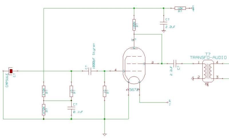
http://i16.photobucket.com/albums/b33/roddycluff/5672mic.jpg
http://msevm.com/retro/01/index.htm
http://www.tforumhifi.com/t7089-1p24b-headphone-amp-otl
http://www.elektroda.pl/rtvforum/topic486011.html
http://obrazki.elektroda.net/86_1264109048.png
http://www.jogis-roehrenbude.de/Leserbriefe/Enricos-Taschenradio/Enricos…
http://www.jogis-roehrenbude.de/Leserbriefe/Vicos_Bleistift-FM-Radio/FM-…
http://www.andreadrian.de/sdr/#mozTocId636563
http://www.radiomuseum.org/forum/russian_subminiature_tubes.html