History
Next -> Bright Emitters ->Dull Emitters
A vacuum tube, electron tube (in North America), or thermionic valve (elsewhere, especially in Britain) and Röhre in German (Adjective/Plural? Röhren as in Röhrenradio = Valve Radio), usually simply called “tube” or “valve”, is a device that uses wires, grids and plates to change current flowing between the heated cathode (source) and collecting Anode.
Almost all valves have a heated Cathode as an electron source and at least an Anode (Plate in USA). To control the current and have something more complicated than a Diode or Rectifier (used to turn AC mains to DC or detect radio signals) you need at least one control electrode, the grid.
- Diode: Cathode and Anode, like semiconductor use, two electrodes or elements
- Triode: One grid (i.e. 3 elements)
- Tetrode: Control grid and Screen Grid. The Screen greatly improved the high
 frequency response by “screening” the Anode from Grid and thus reducing the capacitance which would be internal negative feedback at high frequencies.
 - Pentode: Three grids. A “suppressor” grid is added to control and screen as the Tetrode has a nasty dip in transfer curve at low Anode voltage that can cause oscillation. It’s between the Screen and Anode electrodes. (i.e. 5 elements)
- Hexode: Adds a 4th Grid
- Heptode: Has five grids. Also called a Pentagrid Converter. Usually used as Mixer/Oscillator stage in “superhet” radio. DK96 was used in Battery Radio. (7 elements).
- Octodes and Nonodes exist!
Other variations are Beam switching valves with dual anodes and electrode to “switch” current between them. Used as mixers. Other rarer types are Gamatron (the two electrodes near Cathode are similar and are interchangeable as “grid” and “anode” (plate), Bi-grid (a failure with no real improvement over Triode, more an attempt to bypass patents as the Gamatron was) and Dual Control Grid Pentodes. On the right is RCA’s Illustration of 1940s miniature B7G “button base” Pentode Valve.
A special case is the Kinkless Tetrode or Beam Tetrode. It has the same schematic symbol as the Pentode and does have five elements and a Pentode characteristic. RCA called it a Beam Tetrode perhaps due to patent disputes with Philips over the Pentode. The difference is that the element between G2 (screen grid) and Anode is shaped electrodes and not a mesh or wire grid like the conventional Pentode’s Suppression grid, G3. The ECL82 (PCL82) and ECL86 (PCL86) are in fact really Triode and Beam Tetrode in one tube, not a regular Pentode.
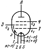 Another Pentode issue is the connection of G3. Triode-Pentodes and other Audio Pentodes may have the G3 internally connected to the Cathode to save pins or cost. This is fine for Common Cathode or Common Anode (Cathode Follower). But on a Grounded Grid (Common Grid) amplifier for RF this G3 would then be a capacitor from output to Input and the amplifier would oscillate. Thus an EF86 (designed as low noise RF amp) has the G3 to a separate pin to allow more flexible use such as Common Grid RF Amplifier. Schematic symbol is of Pentode with outer electrostatic screen and a separate G3 (suppressor grid) allowing common grid Mode. It’s a direct Cathode or Filamentary Valve.
Types of cathode.
The electrons enter the vacuum from the cathode electrode and are attracted by the more positive anode.
- Cold Cathode: The earliest tubes such as 1890s Cathode Ray or Braun tube.
- Directly Heated or Filamentary Cathode: The earliest used pure tungsten or other materials like a light bulb. CFL and regular Florescent tube lighting usually has this.
- Indirectly Heated Cathode: A coated metal tube with an interior insulated heating element. Virtually all valves intended for mains supply use from about 1929.
Early early “bright emitter” valves (invented 1905) used a straight wire filament in a vacuum like the early tungsten light bulbs (invented in 1904 in Hungary), but from 1913 Nitrogen or other inert gases have been used in Tungsten filament lamps. From early 1920s lamp filaments were coiled and GEC developed the coiled coil lamp filament in 1924. Tubes or valves generally have a very hard vacuum, though early types had trace amounts of gas (soft valves) partially because some people believed that was needed for electron flow and partly due to difficulty of making a good vacuum. The “getter” process was invented to remove the last traces of gas.
The cathode can be direct (filamentary valve) or indirect heated. Most mains valves are Indirect as this insulates the Cathode and heater circuits by typically 200V and makes circuit topologies thus more flexible and avoids mains hum with AC driven heaters. Most Battery valves use direct filaments as these use less power. Transmitter or other high power valves may be direct types.
Filaments construction may be bare Tungsten (now only very high power on new valves) and for a while on battery valves Nickel was used due to the fragility of Tungsten. Filament was then coated with Thorium for better performance and later a Barium Oxide formulation, or other oxide mixes. Indirectly heated cathode is usually Nickel or Molybdenum coated with oxides.
Heater or filament voltages are from 1.2V to 45V and currents from 11mA to many amps. Grid voltages are usually a few volts below the cathode (effectively negative) which can be achieved using a series resistor between cathode and 0V (ground) or a negative supply. Grid voltages can be as low as -25V or even as high as +5V (high pulsed powers) compared to cathode. Anode voltages can be 6V to 50,000V but 120V to 400V is typical for mains equipment valves. Battery Valve gear was typically 22.5V, 30V (hearing aids), 45V, 67.5, 90 (Most 1950s portables) and 120V (pre- 1940s with 2V filaments) with typically 1.2, 1.5, 2V, 6.3, 7.5 or 12.6V filaments. Some valves in car radios used only 6V or 12V anode HT.
A traditional “deep” TV screen is a Cathode Ray Tube (CRT) where the electron beam fires past the Anodes to a phosphor screen. The beam is deflected by electromagnets (coils) or internal electrodes (usually only Oscilloscopes).
The Blue/Green glowing displays on many DVD, BluRay and Set-boxes for TV are triodes like miniature CRT. The Cathode is 2 to 8 fine heater wires just behind the glass and the illumination is from phosphor coated Anodes. The display can use less pins by having “multiplexing” using fine metal gauze like grids between the cathode filaments and the Anodes.

2011 Triode Valve (Multiplexed Vacuum Fluorescent Display) in a DVD Player
To find valve radios in Germany on Ebay (most of the best 1960s models with VHF-FM, and even stereo) you may need to search for Röhrenradio.
Why transistors were not called “solid state Triodes”, though silicon & germanium Rectifiers are called diodes?
I think because the transfer characteristic is more like a Pentode and early transistors were poor and sold on different merits than “Triode” replacement.
Battery valves
We could say there are 11 generations of Battery Valve Radio:
- 1905 to 1920s using pure tungsten “bright emitters”. LT is Lead Acid Accumulator (typically 6V via rheostat for each filament ). Often HT is a tray of 60 small lead Acid Accumulators.
- 1920s using thoriated tungsten. LT is Lead Acid Accumulator (typically 6V via rheostat for each filament )
- Table top mid 1920s and early 1930s. LT is Lead Acid Accumulator (2V, 4V or 6V)
- Transportable late 1920s to 1930s. We also have development of 6.3V filament for Car Radio as cars then use 6V battery, switching to 12V later. 6.3V becomes the “standard” for Mains radios. Some models use early design “vibrator” pack for HT via the low voltage Lead acid rechargeable battery. Car radios up till 1950s use vibrator packs to generate the HT. Only the very earliest models don’t run off the car battery. HT is 48V, 67V, 90V or 120V dry cells (Zinc Carbon battery). LT is Lead Acid Accumulator (2V or 4V). The 2V filament tube radios for fixed use in homes with no electricity to use a Lead Acid Accumulator for LT are produced till 1950!
- 1938 All dry Octal “50mA” tubes (Sylvania). 1.4V dry cells instead of 2V Accumulator. Used up till 1948 in new models in UK due to shortages of miniature tubes.
- 1940 Miniature B7G “50ma tubes” Portable (RCA IT4 etc = later DF91) inc miniature WWII Covert receivers. 1.4V filament. Late 1940s and Early 1950s in Europe. Series or parallel.
- Telefunken metal Y8 battery tubes All different filament currents. Often later NiCd for LT supply. Parallel only.
- Mid 1950s “25mA Valves” Portable mostly with DK96, DF96, DAF96, DL96. Typically 125mA @1.5V or 50mA at 7.5V DC LT filament supply and 67V or 90V HT battery pack using 5mA to 8mA. So about x2 life on HT and LT batteries. Much longer than modern DAB radio!
Overlapping 3 to 5 we have the DK41, DF41, DL41, DF92, etc variations. Also we have 6.3 filament valves optimised for HT of 12V in car Radio. Usually a early Germanium transistor audio output stage.- USA and Japan Subminiature tubes for military and hearing aid use are used in Pocket Radio sets.
- Late 1950s with VHF-FM adding DC90 then DF97. Often using “DEAC” early type of NiCd to regulate filament voltage on mains and as rechargeable LT battery. A 90V HT dry cell used.
A few models use the DM70 or DM71 “magic eye” used in Mains sets and tape recorders since 1954. Portable tape recorders in 1950s use DF91, DL91, DF96, DL96, DM70 etc.- Mid 1950s to late 1980s Russian Military Radio only. Sub-miniature Russian Rod Pentodes. Transistor inverter or vibrator pack for HT.
Filament Development
The original valves unsurprisingly used tungsten lamp filaments. The then obsolete carbon filament was tried too. The filament had to glow quite brightly to have enough emmision of electrons, hence “Bright Emitter”. To improve filament life and reduce power consumption was obviously one important research goal.
Package and Base Development
The first valves or vacuum tubes used existing incandescent electric lamp glass envelopes, pinched glass base and modified lamp bases for connections.